Deskinator
An end-to-end tabletop-cleaning robot that turns touchless edge sensing into a fitted workspace, a safe coverage plan, and measurable motor commands.
- Role
- Sole designer and developer
- Stack
- Python / NumPy / Raspberry Pi / APDS9960 / A4988 + NEMA17 / RANSAC + PCA / Coverage planning / Matplotlib
- 48
- retained simulations
- from a reported 50-run campaign
- 99.40%
- mean safe-inset coverage
- σ 0.70% in idealized simulation
- 137.22 s
- mean simulated cycle
- σ 3.57 s; target was 120 s
Scope and ownership
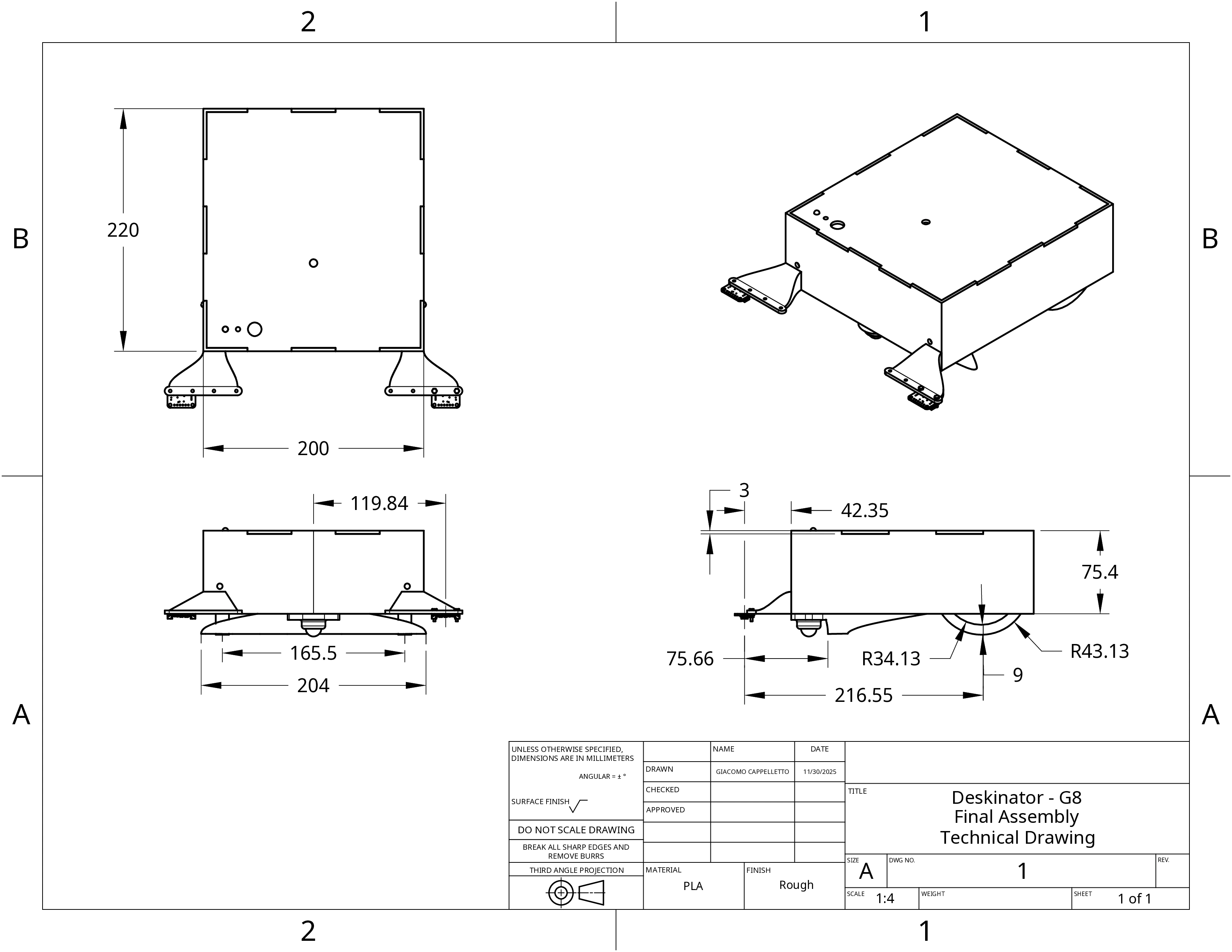
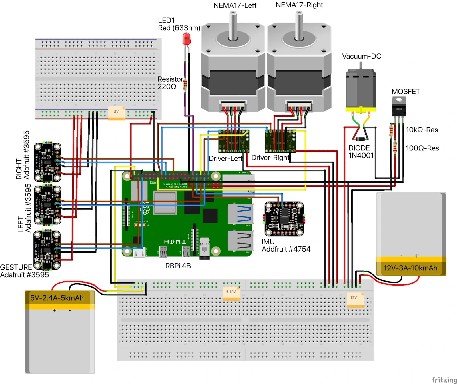
Deskinator was a self-directed robotics build around a deceptively strict brief: create a compact, touch-free vacuum robot that can start with a hand gesture, discover an unknown rectangular tabletop, clean it without crossing an edge, and aim for a two-minute cycle. I designed and implemented the complete system—from electronics and mechanical integration through the Raspberry Pi software, simulator, analysis, and final documentation.
Rather than assuming a known map, the robot earns one. It follows the boundary, records where its two front sensors lose the surface, fits a rectangle, contracts that rectangle using the physical sensor-to-vacuum geometry, and only then executes a coverage path. Safety is therefore a property of perception and planning, not a last-second motor stop.
One inspectable control loop
The supported new-alg executable is deliberately organized around one synchronous 50 Hz loop in DeskinatorSimple.run(). Every cycle checks the gesture stop, reads edge sensors, advances differential-drive odometry from step counts, evaluates the state machine, commands the motors, rasterizes the vacuum footprint, and writes telemetry. A shared time base makes a failure traceable from sensor sample to actuator command.
The executable states are explicit: WAIT_START, BOUNDARY_DISCOVERY, COVERAGE, and DONE. A failed rectangle fit enters DONE; a stop gesture exits the active loop into the same safe-shutdown path. Optional IMU and EKF files remain experimental scaffolding; the supported default path uses stepper odometry.
From proximity to geometry
Two front APDS9960 sensors report whether the surface is present. The filter combines a raw threshold, an exponentially weighted moving average, hysteresis, and 60 ms debounce before an observation can become an edge event. Each event is projected into world coordinates from the robot pose and measured sensor offsets, preserving which physical reading produced each boundary point.
After the robot closes a lap, SimpleRectangleFit extracts candidate lines with a 2 cm RANSAC inlier threshold, refines each direction with SVD/PCA, searches for orthogonal four-line combinations, and scores how well they explain the observations. A coarse 5° angle search provides a fallback when the line combination is weak.
From geometry to motion
CoveragePlanner derives a safe inset from the sensor-to-vacuum offset, then lays lanes along the rectangle’s longer dimension. A 0.20 m cleaning width with 0.02 m overlap controls the lane spacing. The planner evaluates four traversal variants to reduce the distance from the current pose, alternates lane direction, adds explicit turn transitions, and finishes with a perimeter pass.
The drive-then-turn controller turns those oriented waypoints into linear and angular velocity commands. StepperDrive converts them to wheel rates, applies acceleration-aware updates, and emits 1/16-microstep pulses through A4988 drivers. In parallel, a 5 mm SweptMap raster and CSV telemetry expose where the modeled vacuum actually traveled.
Evidence, with boundaries
The reported 50-run simulation campaign retained 48 completed trials. On an ideal 2 m × 2 m table with randomized starting poses, those runs averaged 99.40% coverage of the safe inset and 90.97% of the full modeled tabletop. Mean completion time was 137.22 seconds, so the planner missed the two-minute target even while producing strong simulated coverage.
- The simulator uses deterministic unicycle dynamics and does not model sensor noise, wheel slip, battery sag, or surface variation; these are simulation results, not physical-cleaning claims.
- Rectangle fitting and coverage planning assume a rectangular tabletop.
- The source workbook’s stale summary and invalid rectangle-error field are excluded; the published statistics come from the 48 retained raw rows.
- Physical performance remains sensitive to surface reflectivity, wheel traction, sensor placement, and battery state.
Executable architecture
One loop from edge reading to evidence.
The final report captures several earlier design directions. This diagram follows the code that actually runs on the new-alg branch: a compact control loop with explicit data ownership, plus a separate StepperDrive pulse thread confined to the hardware timing boundary.
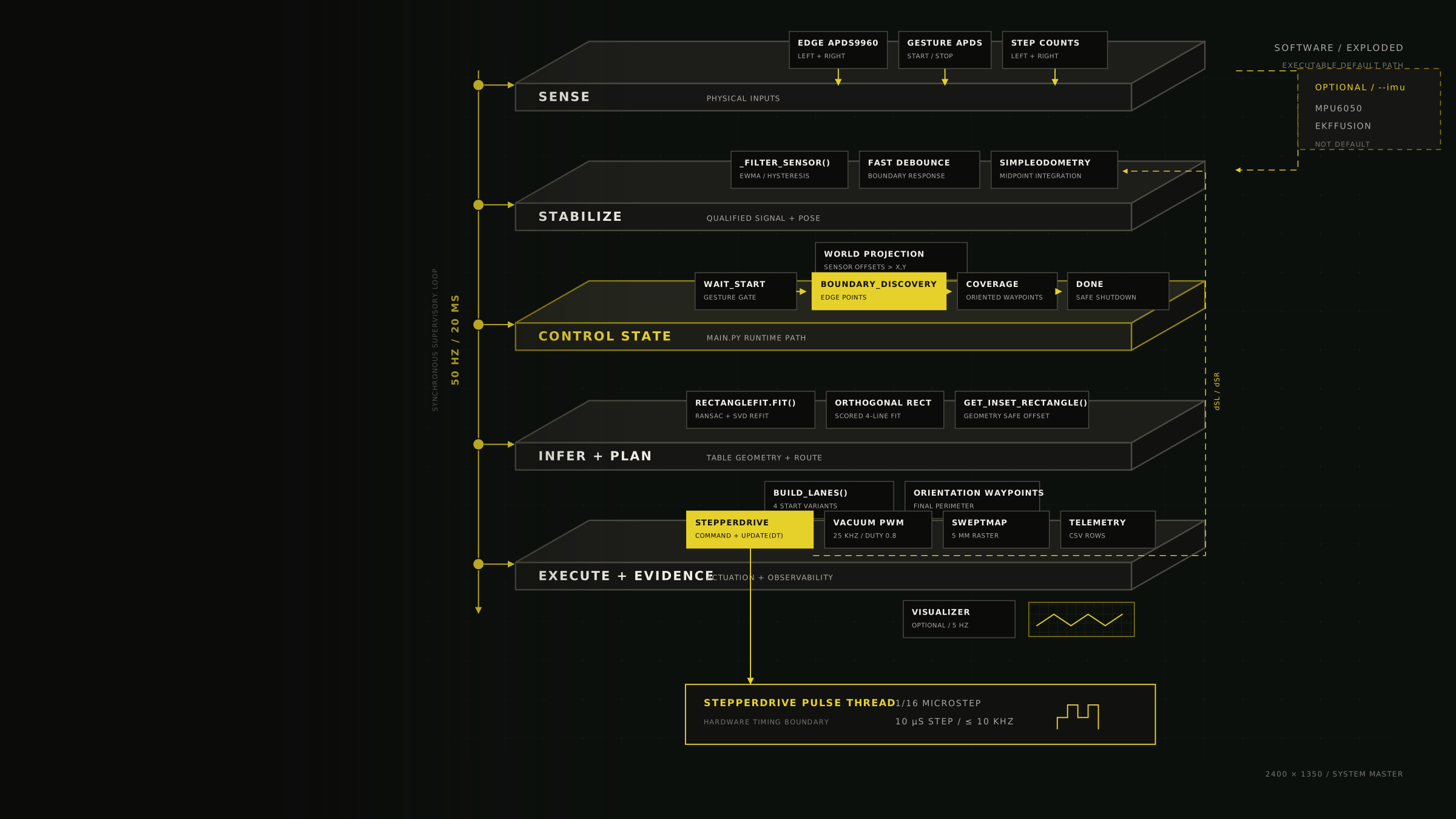
01 / Sense
Hardware inputs
APDS9960 + step countsTwo front edge sensors, a dedicated gesture sensor, and STEP-pulse counters provide the loop’s observable inputs.02 / Stabilize
Signal and pose
_filter_sensor() + SimpleOdometryThresholding, EWMA, hysteresis, and debounce qualify edge events while differential-drive integration updates pose at 50 Hz.03 / Infer
Workspace and route
SimpleRectangleFit + CoveragePlannerWorld-frame observations become an orthogonal rectangle, a geometry-derived safe inset, and oriented coverage waypoints.04 / Execute
Motion and evidence
StepperDrive + SweptMapVelocity commands become motor pulses while a 5 mm raster, CSV telemetry, and diagnostic plots record the outcome.
Sensor events and step counts meet in the same 20 ms cycle. That makes the route from physical observation to command and log row straightforward to replay, while low-level STEP pulse generation remains behind the StepperDrive boundary.
Controller state
Progress is explicit. Failure is a state transition.
- 01
WAIT_STARTGesture-gated idle; motors and vacuum remain off.
- 02
BOUNDARY_DISCOVERYReact to edge state, collect world points, and close one lap.
- 03
COVERAGEFit the table, generate lanes, and advance oriented waypoints.
- 04
DONEZero commands, stop the vacuum, and close the evidence trail.
- Start gestureWAIT_START → BOUNDARY_DISCOVERY
- Rectangle fit failureBOUNDARY_DISCOVERY → DONE
- Stop gestureActive loop → safe shutdown
- Coverage completeCOVERAGE → DONE → safe shutdown
Engineering pivots
Hardware failures changed the software architecture.
Two of the most valuable results were redesigns, not headline metrics. Each forced the implementation to respect an electrical constraint that a simulator could not reveal.

Decision 01 / sensor topology
Make the I²C layout part of perception.
Shared multiplexer; fixed addresses; corrupt, latent reads.
Isolated hardware and software buses plus a gesture bus.
Fewer sensors produced a more trustworthy boundary signal because bus ownership and polling latency became deterministic.
Decision 02 / motor drive
Design motion around current and pulse timing.
Thermal and current mismatch caused jitter and lost steps.
Current limiting, 1/16 steps, ramped commands, 10 kHz cap.
The controller now respects a 10 μs STEP pulse and the motor current envelope instead of treating wheel velocity as an abstract output.
Simulation evidence
Useful numbers start with a test contract.
These plots come from 48 retained completed simulations in the reported 50-run campaign. They validate geometry and route generation under controlled assumptions; they do not substitute for physical cleaning trials.
- Workspace
- Ideal 2 m × 2 m table
- Initial condition
- Randomized starting pose
- Dynamics
- Deterministic unicycle model
- Unmodeled
- Sensor noise and wheel slip
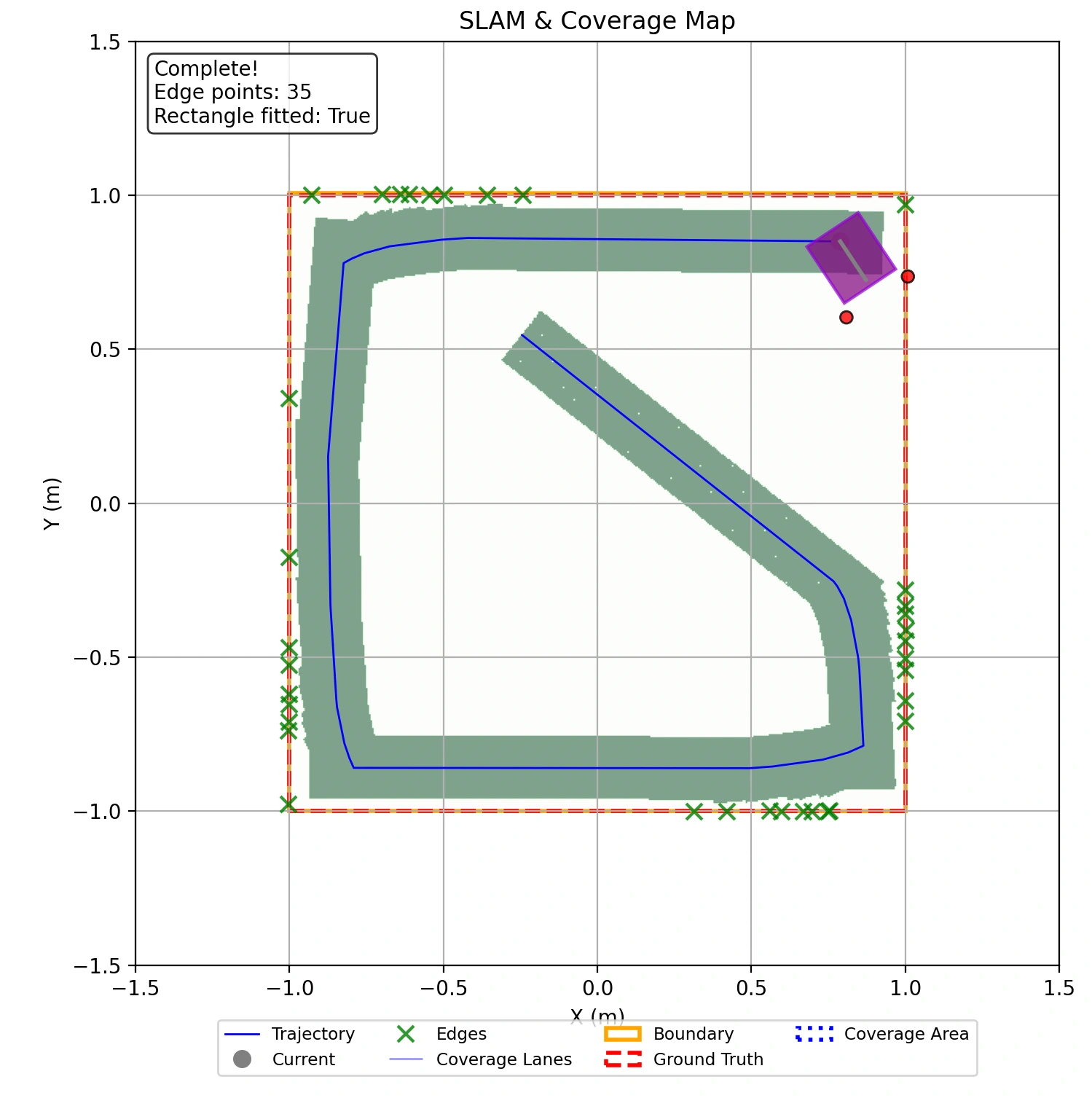
Boundary observations are stored in world coordinates, then explained by a scored orthogonal rectangle.
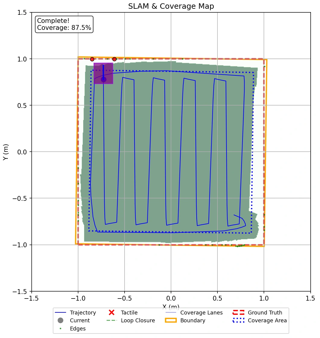
The planner contracts the sensed table before laying alternating lanes and a final perimeter pass.
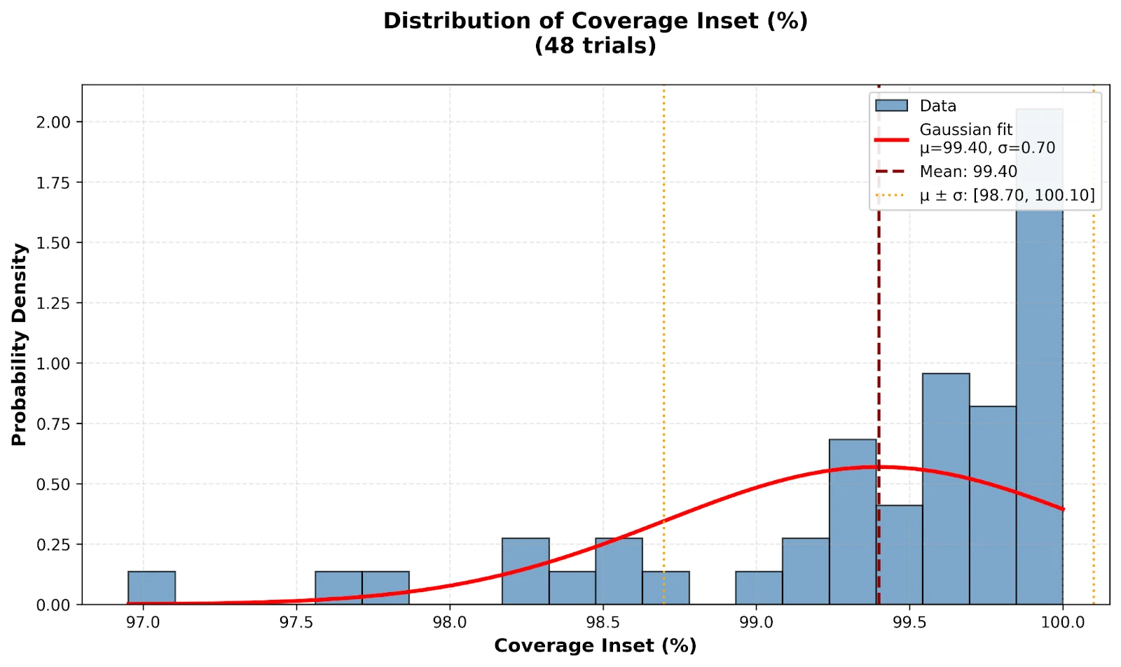
Safe-inset coverage averaged 99.40% with a 0.70% standard deviation and a 96.95–100% range.
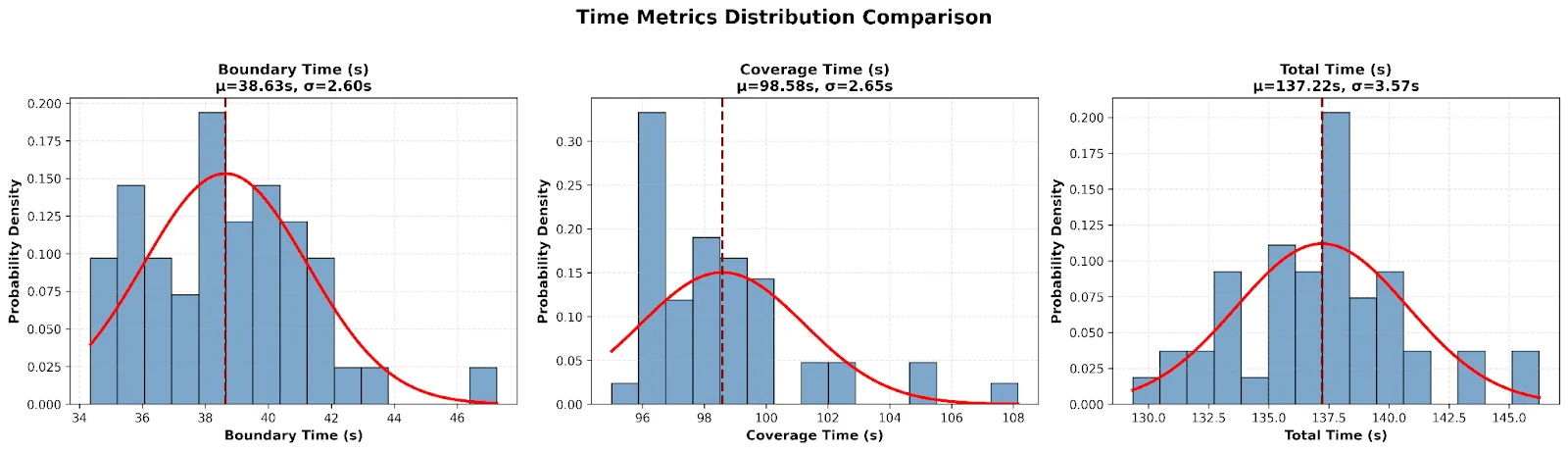
Mean simulated completion was 137.22 s (σ 3.57 s; range 129.35–146.25 s), exposing a clear speed shortfall.
Project record
Read the paper. Inspect the source. Open the drawings.
The case study is an index, not a substitute for the underlying work. The final report, drawing, executable branch, and raw simulation artifacts are linked directly below.